|
|
SensorGnome - fresh data from the field to your plate > Automated VHF Telemetry > 4. Receiver Station Set-up > Settting up an Automated Radio-telemetry Station
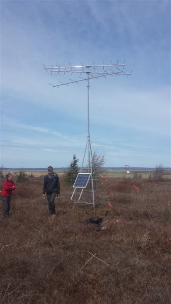
Settting up an Automated Radio-telemetry Station Settting up an Automated Radio-telemetry StationEdit From $1Automated Receiving Station/Tower Setup GuideApril 2014Note: There are many different ways to build an automated radio-telemetry station. This page provides details on how to setup a station using a 30' pop-up tower. Don't forget to read the rest of detailed instructions elsewhere on www.sensorgnome.org. CLICK ON PICTURES FOR LARGER IMAGES. Tools you may need: · Sledge hammer (for driving rebar) . Knife and/or scissors · Ratcheting wrench set · Crescent wrenches · Socket set · Flat-headed and square-headed screw drivers · Vice grips (or channel locks) · Wire cutters (may double as crimpers for aluminum sleeves) · Wire tightener handle (http://www.gallagher.ca/fence_tool.aspx?mktprodid=4079) · Measuring tape (this style and at least 42 ft in length: http://www.canadiantire.ca/AST/browse/6/Tools/MeasuringTools/Tapes/PRDOVR~0577018P/Mastercraft+Fibreglass+Tape.jsp?locale=en) · Multi-meter (Digital or Analog)
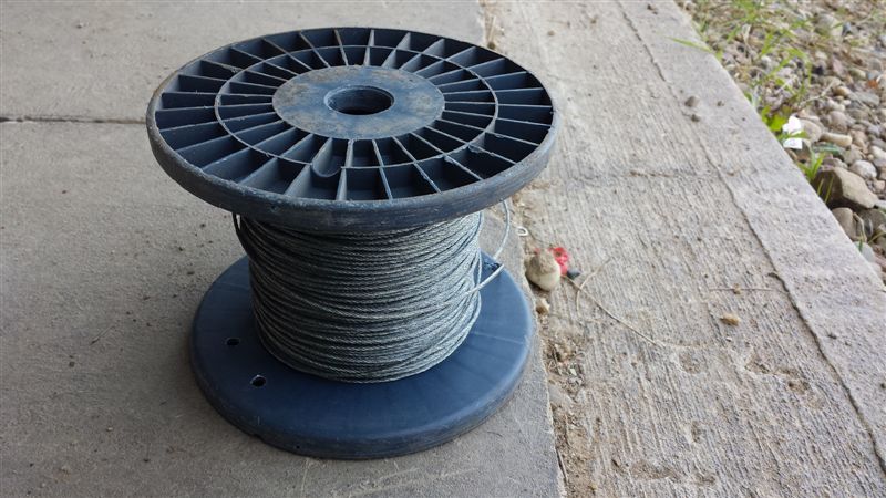
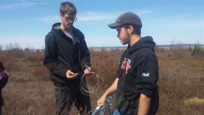
BEFORE GOING INTO THE FIELD· Prep guy wires: - Cut 3 pieces of aircraft cable of each length: 16ft, 30ft, 42ft (9 cables total)
- Colour-code guy wires according to length using coloured electrical tape; this will prevent mixing up of lengths in the field
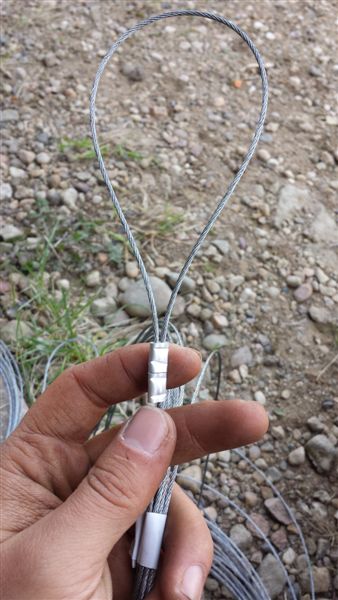
- At both ends, create loops from last ~ 20 cm of wire; secure each loop with 2 aluminum sleeves (crimps); avoid leaving tag ends exposed, otherwise they will fray and stab your fingers
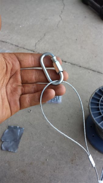
- Attach a quick link to one end of each guy wire
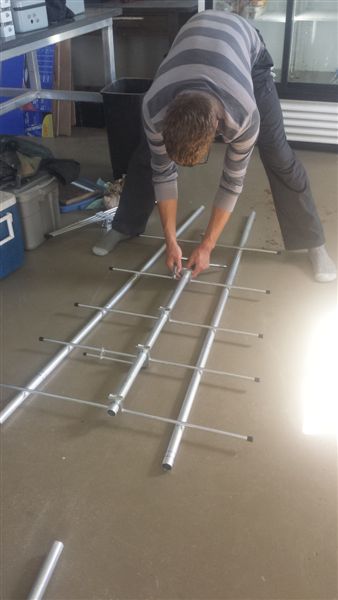
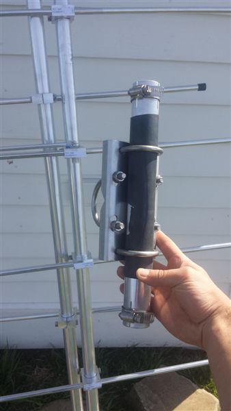
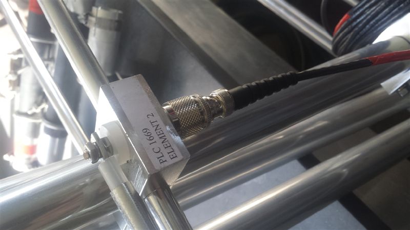
· Assemble antennae: - Assemble antennae according to instructions; make sure that PL-259 connector on element 2 is facing inwards (i.e. towards element 3). NOTE: Some antenna manufactured by Laird Technologies were mislabbelled - with element 6 in the positiion where 9 should be. Element 9 should be located closest to the tip of the antenna (despite numbering on pole). - The easiest way to ensure that all of the elements are on the same plane is to lay the antenna on the floor (or any other flat surface) - using two metal poles to level the elements works well
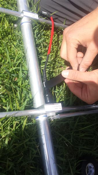
- Wrap connector with rubber; this can be an old bike tube, piece of inner tube, etc.
- Attach coax cable to element 2; in order to fit the rubber cap over end of coax cable you’ll need to cut an ‘X’ in the small end
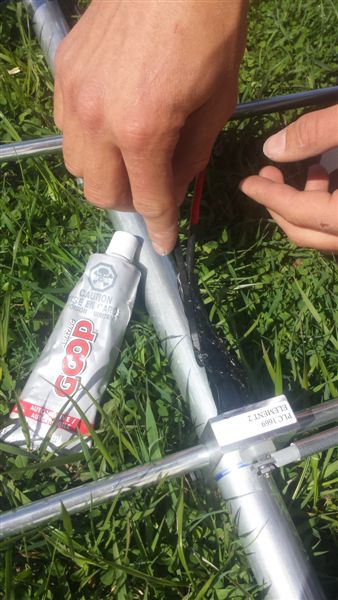
- Once coax cable is screwed into PL-259 connector and rubber cap has been slid over the connection, wrap the cap with electrical tape or silicone tape and then finish sealing with marine goop or silicone
- Lastly, zip tie the coax cable to the antenna boom - Loosely attach mounting plate to antenna; plate should be perpendicular to elements . Assemble solar panel - If using separate stand, simply bolt each side of the stand onto the solar panel and connect the two sides of the stand using the crosspieces - If attaching solar panel to tripod (recommended), dismantle the solar panel stand, leaving only the two main arms of each side connected to the stand. Bolt these pieces onto the solar panel and fold up the new stand for easy transport
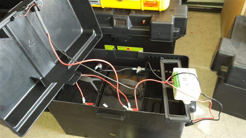
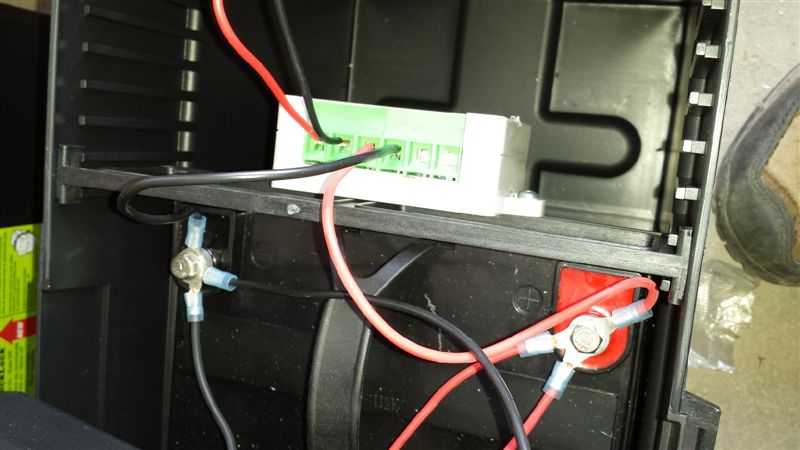
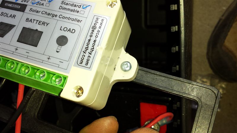
. Assemble batteries - Two cells can fit into one battery case - ensure they are lined up properly - Connect cells in series - be careful not to complete a circuit as you will get a painful shock! Be sure to connect positive to positive and negative to negative.
- Connect built-in voltmeter and charge controller connection to the cell closest to the divider
- Connect battery to charge controller, then connect solar panel cable to charge controller
- Screw charge controller on to battery divider, then close battery lid
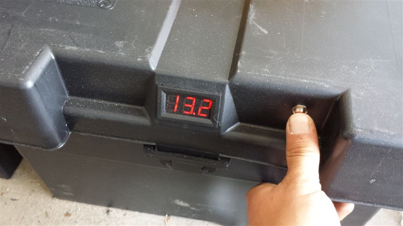
- Ensure the voltmeter is working
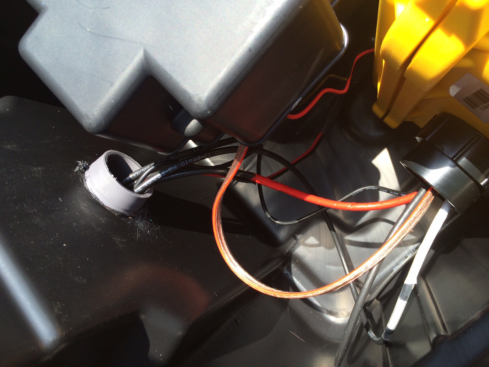
· Drill hole in plastic bin (Action Packer) and insert plastic elbow for the coax cables and cable from solar panel ON-SITETower set-up
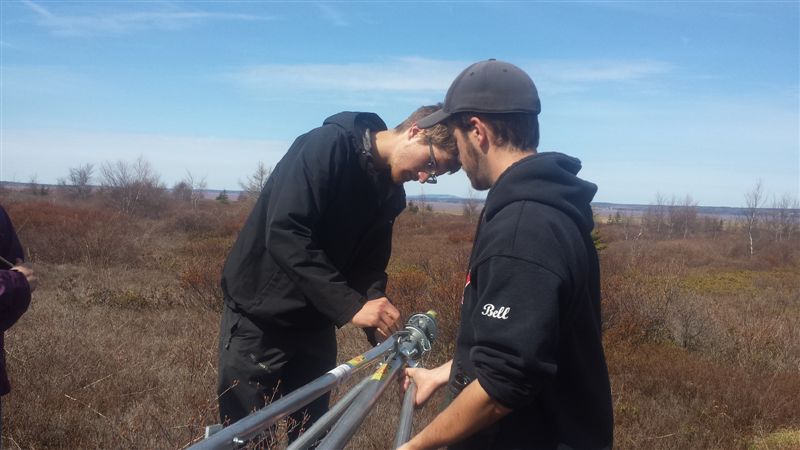
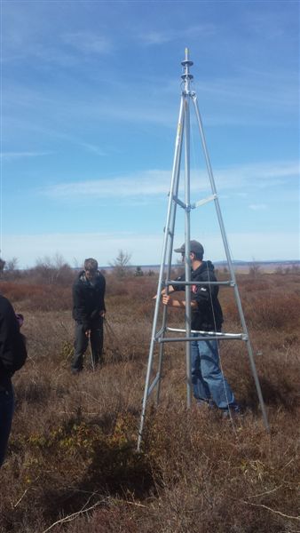
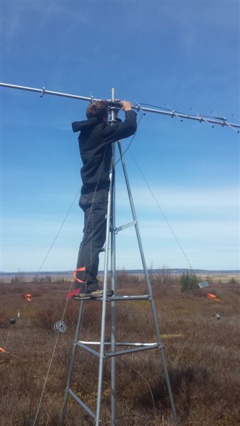
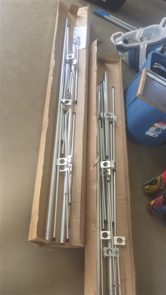
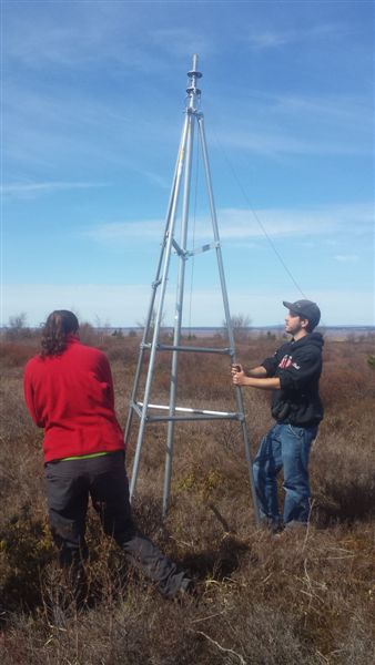
· Assemble tripod according to instructions
· Finish assembling antennae by connecting the two halves and tightening hose clamps on the connectors · Insert pop-up mast into tripod, attach guy wires to lowest guy ring, and stand up/position tripod
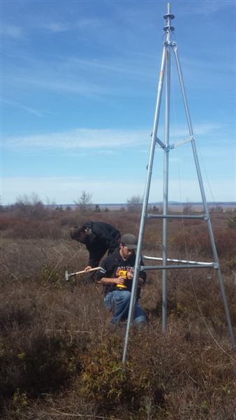
- DO NOT CLIMB the tripod at this point unless it is being supported by someone - It’s important to have the tripod as level as possible at this stage; if unlevel, will be exaggerated when the mast is popped up - The bottom of the pop-up mast should be touching the ground; not sitting in the middle bracket of the tripod - If using solar to power SG, consider the direction that the face of the tripod to which the solar panel attaches (Ladder, in our case) should be facing to achieve maximum light (typically south) · Anchor the rebar 7’, 14’, and 21’ (70% of respective guy wire heights) from the base of the pop-up mast (not the tripod) in 3 directions spaced 120 degrees apart; the 3 legs of the tripod are a useful guideline for getting the right spacing
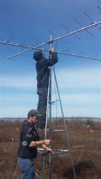
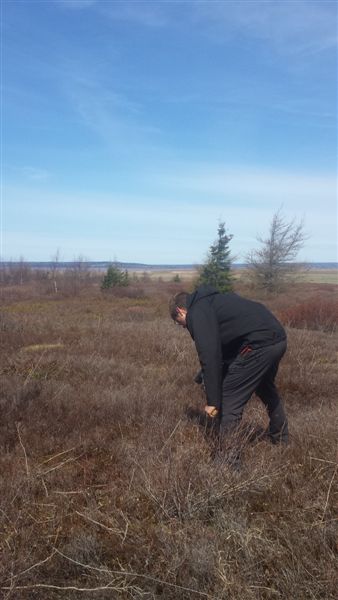
- In particularly windy areas, having guy wires in 4 directions is advisable · Attach the bottom 3 (or 4) guy wires to the closest rebar and tighten with wire-tighteners. At this point the tripod should be safe to climb. Make sure to flag all rebar and guy wires at this point.
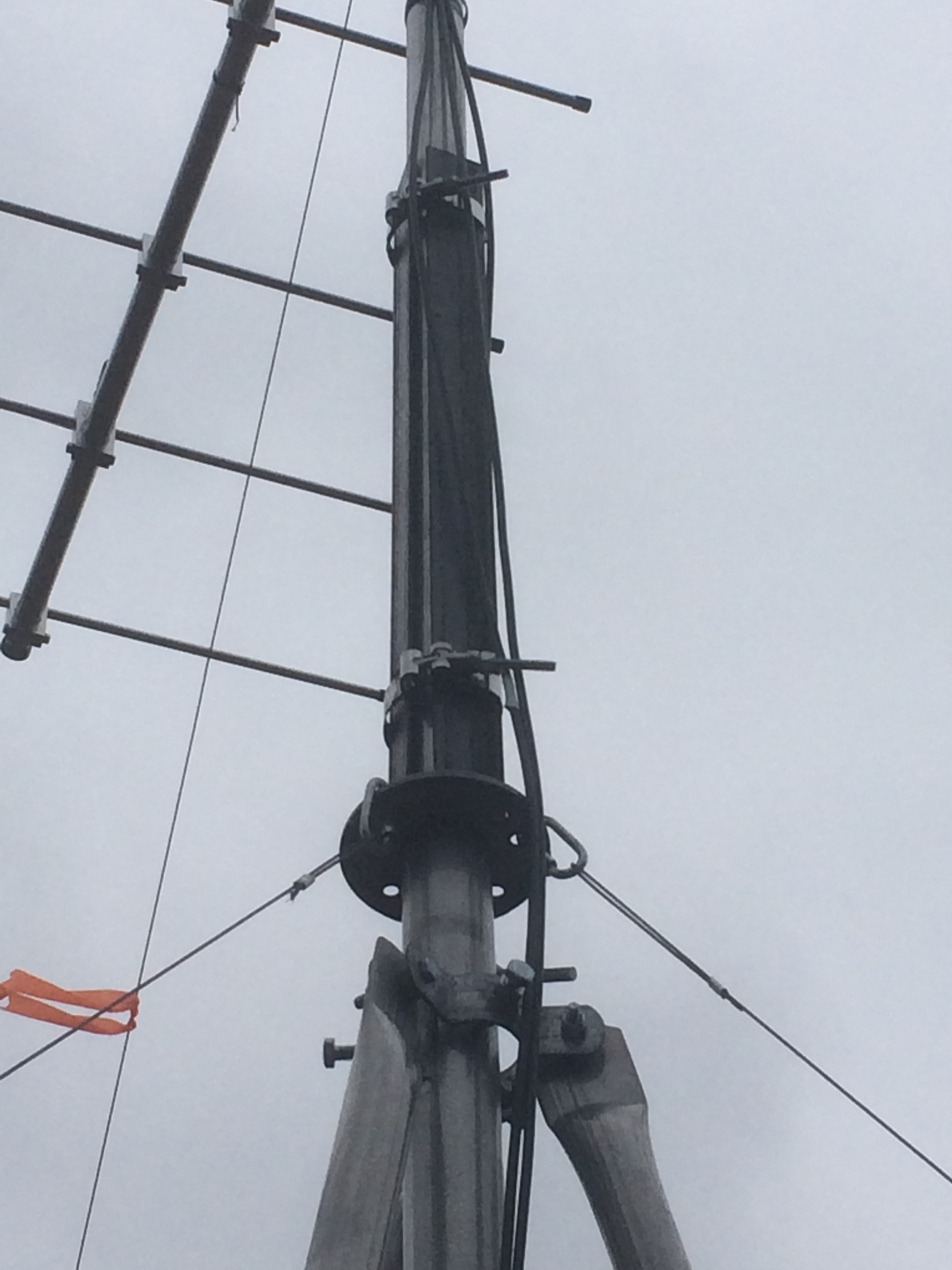
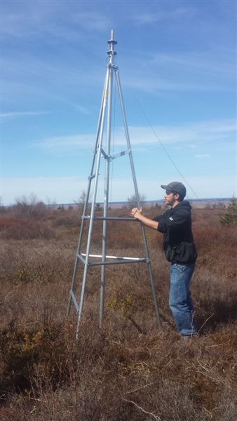
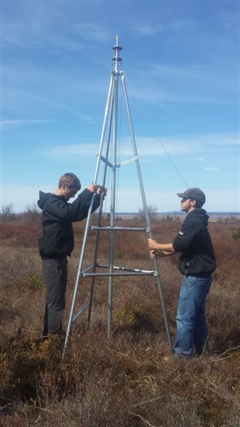
· It’s almost time to attach antennae, but first ensure that the upper guy ring is sitting above the support (below):
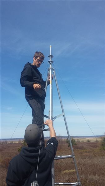
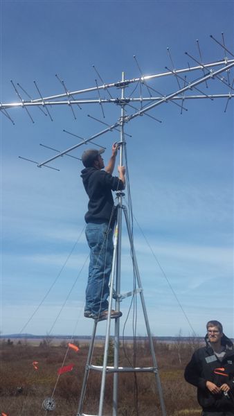
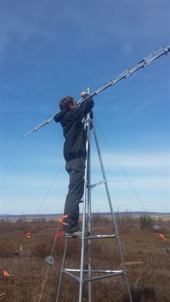
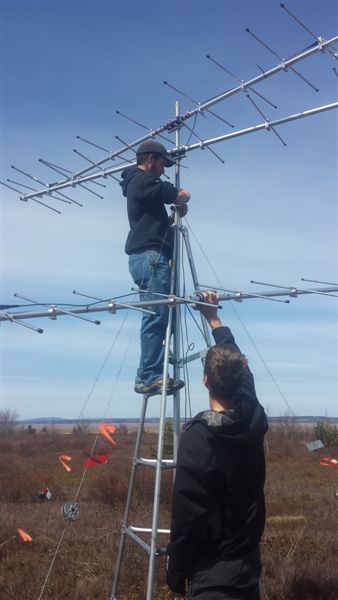
· Attach the first antenna to the very top of the uppermost section of the mast; raise the upper most section of the mast ~ 0.5m; attach second antenna; if attaching a third antenna, raise the mast another 0.5m and attach antenna. **It is ideal to leave as much distance between antenna as possible, >1m or more if space allows, especially for antenna in the same place (eg. E & W facing antenna). **
- Antenna elements should be horizontal, ensure that all elements are still tight and lying in the same plane - The top 2 guy rings need to sit BELOW the lowest antenna Wind Damage Protection: To avoid potential damage in excessive wind, 2 pieces of 2' angle iron reinforcements can be affixed to the mast with pipe clamps for about $25/tower. 2' sections of the appropriate size, and pipe clamps, can be found or ordered from your local hardware store.
Despite hundreds of deployments without incident, problems sometimes occur. In this case the failure was prompted by a hurricane. The solution:
Poor picture will be replaced shortly. Antenna Orientation: At this point you'll want to ensure that the antennae are correctly oriented with respect to one another. Their exact direction does not matter at this point. Once the pop-up mast is fully extended and secured with guy wires, the mast can twisted inside the tripod to achieve the appropriate geographic directions. A typical setup that may ensure the best broad coverage of an area would be to have the antennae oriented North (0°), Southeast (120°), and Southwest (240°). Important: The orientation of antenna at a given station depends largely on the geography of the area and the questions being asked. Most often the goal is to cover as much ground as possible while being able to detect movements from one space to another. This is usually best done through the creation of 'walls' or 'fences'. When building an array the stations function best when antenna from multiple stations are pointing at each other. So it may be desirable to have an antenna from two stations positioned 10-30 km apart pointing directly at one another. This essentially forms the wall or fence. This is particularly useful for covering shorelines or detecting movements between two otherwise uncovered regions. Figure1. shows an example of an array in southern Ontario.
Figure 1. Sample orientation of antenna in southern Ontario. Note: Arrows do not represent actual detection distance.
· Once all of the antennae are attached, secure the top guy ring just below the bottom antenna · Attach one end of the remaining 6 (or 8) guy wires to the top two guy rings; attach the other ends to the appropriate piece of rebar anchor · It’s now time to raise the mast - The person who raises the mast needs a pocketful of zip ties, clippers, and vice grips; work gloves are also recommended to protect hands from getting jammed/cut on the mast - Extra field hands should apply loose tension to the guy wires while the mast is being raised; apply enough tension to keep the mast from wobbling back and forth too badly, but not so much that it hinders the person raising the mast · Raise the mast - As you're raising the mast, use zip ties to secure coax cables to the mast to prevent them from flopping about in the wind; 2 zip ties per section is plenty · Once the mast is raised, tighten the guy wires using the wire tighteners. The person that raised the mast normally does the first round of tightening while the others keep holding the guy wires to maintain stability until all guy wires are somewhat tight. - It may take several rounds of tightening to create equal tension among the different guy wires; the wires should be tight, but don’t have to be guitar string tight · At this point the mast can be twisted to orient the antennae; once oriented, tighten bolts at the top of the tripod and middle of the tripod to prevent the mast from twisting in the wind
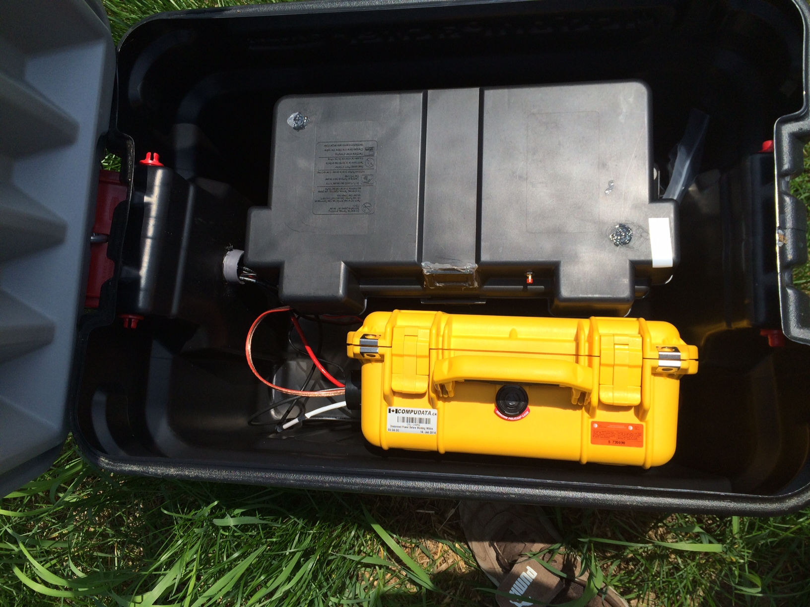
Solar module and SensorGnome (details may vary depending on exact equipment, manufacturer and specifications)
· Build a stand, place solar panel on the ground, or preferably attach solar panel to the tripod (usually facing south). Run all of the antenna cables, gps cable, and power source cables into a box or container holding the sensorgnome and batteries.
· Put batteries in Rubbermaid 24 gal Action Packer and connect in PARALLEL (+ to + and - to -)
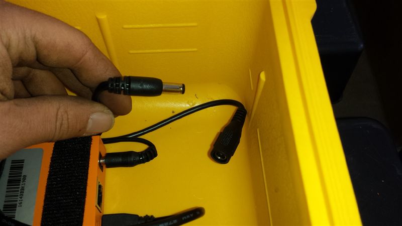
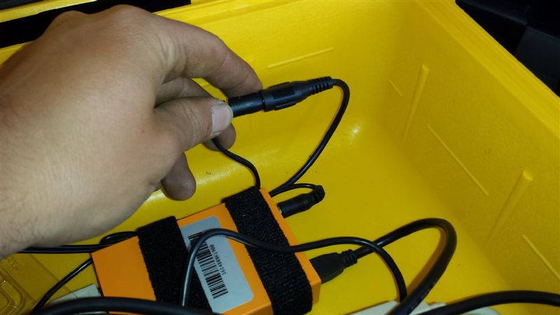
· Connect batteries to charge controller, then connect solar panel to charge controller · In SG, disconnect DC plug of the Y-cable (Fig 1), which provides power to the BeagleBone and USB Hub
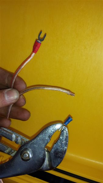
· Pull U-connector off SG power cords with pliers to expose copper wire. Feed through SG hole and attach to charge controller
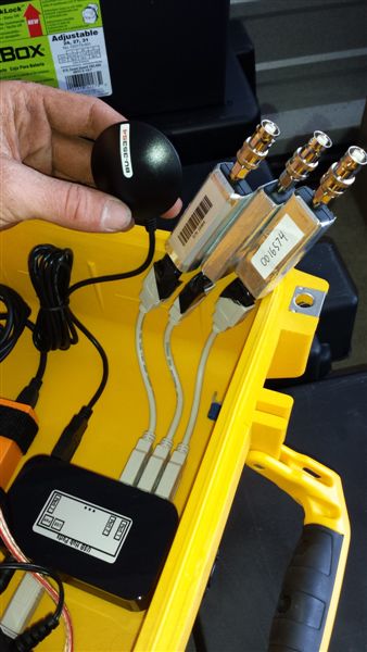
· Attach FunCube Dongles to Ports 1-3 in USB hub. Feed GPS through hole in action packer and SG and plug into port 7 - Wrap connection between FunCube Dongle and USB extension cord to prevent dislocation
· Connect coax cables to FunCube Dongles
- Carefully record which antennae (e.g. N (red), SW (black), SE (white) are connected into which SG port (We’ve been connecting red to port 1, white to 2 and black to 3) · Reconnect DC power plug. The SensorGnome uses a small computer called the beaglebone, in our SensorGnomes they are in an orange box. Look for a green light on the USB Hub and a blue light 'heartbeat' from the BeagleBone (visible through connector holes and vent)
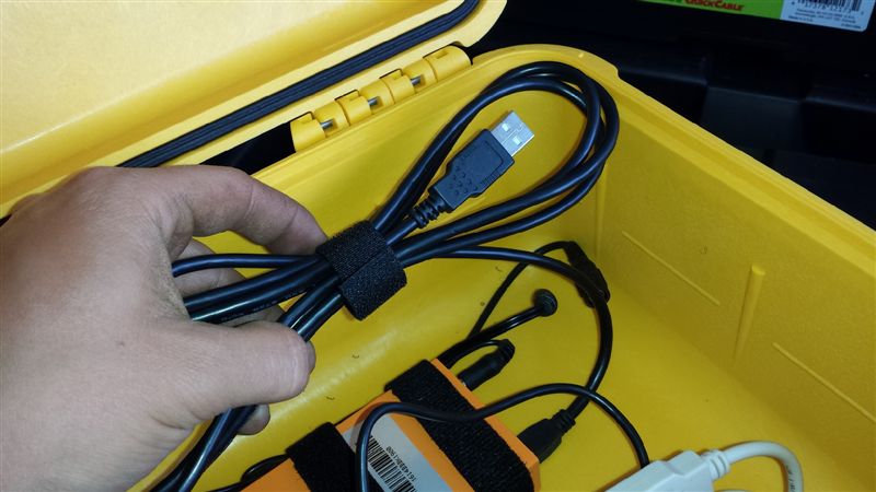
- NOTE: Only after the BeagleBone has power can you connect your laptop · Connect Laptop using the provided mini A to standard A USB cable attached to the beaglebone and coiled up in the case.
· Open Network and Sharing Center. The SG should automatically form a LAN connection with your computer - install drivers if this is your first time connecting · Open “My Computer” and click on “Map Network Drive” (In top toolbar). Add “\\192.168.7.2\boot” as the folder name. This should only have to be done when connecting to your first SG, after which the deployment files can be accessed as a device under “Network Connections” in “My Computer” · Click on the SG Boot device. Right click on the first file labelled “deployment” on open with WordPad. The first 8 lines should be as follows:
{ "info": "default deployment", "who": "who is responsible for this deployment", "contact": "contact information for responsible party", "shortLabel": "changeMe", "acquire": { "gps": { "secondsBetweenFixes": 300
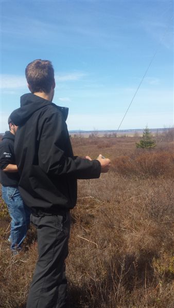
· Change info, who, contact and short label without adding spaces (use underscores) or changing any punctuation in the file (quotation marks and commas should not be over-written). Ie: { "info": "Old_Cut_Deployment", "who": "MOTUS", "contact": "Stu_Mackenzie_BSC", "shortLabel": "OldCut", "acquire": { "gps": { "secondsBetweenFixes": 300 }, · Save over the deployment file on the beagleBone. (Save as, replace). Then save a copy to your laptop for your records. · Disconnect Laptop, then reboot SG by unplugging the beaglebone power, waiting 5 s, and replugging. Reattach your laptop. · Insure the LAN network has been established then open the following using Mozilla FireFox: http://192.168.7.2 · The I am your SensorGnome page should open. Ensure that the GPS is connected and date and time are showing (time is in UTC not EST). Check that all three antennae and GPS are listed in the right USB ports under devices. Make sure the deployment file labels have been changed. - Warning: a live web interface is your only guarantee that the SensorGnome is actually working. Do not deploy if you can't attach. · Turn on test tag and tell the three antennae to listen and make sure tag is being picked up. · Zip tie GPS antenna to tripod. Close
Carefully walk away as to not disturb anything...
Table of parts for a standard 30 ft telemetry tower:
* To date we have only used galvanized and it has worked fine. Stainless is more corrosion resistant and so may be a better long term investment, but it is also more expensive than galvanized. It might be worth getting a quote for both. ** If the quick links aren’t molded properly it can be difficult to fit them through the holes in the guy rings on the pop-up mast. I always bring a guy ring to the store and test each quick link individually to make sure it fits before I purchase.
One-time-use materials:
IMPORTANT! In order for stations to be compatible with Motus, each receiver setup must be registered with at Motus.org. An example Motus Station Station Inspection Form
Was this page helpful?
Tags: (Edit tags)
|
||||||||||||||||||||||||||||||||||||||||||||||||||||||||||||||||||||||||||||||||||||||||||||||||||||||||||||||||||||||||||||||||||||||||||||||||||||||||||||||||||||||||||||||||||||||||||||||||||||||||||||||||||||||||||||||||||||||||||||||||||||||||||||||||||||||||||||||||||||||||||||||||||||||||||||||||||||||||||||||||||||||||||||||||||||||||||||||||||||||||||||||||||||||||||||||||||||||||||||||||||||||||||||||||||||||||||||||||||||||||||||||||||||||||||||||||||||||||||||||||||||||||||||||||||||||||||||||||||||||||||||||||||||||||||||||||||||||||||||||||||||||||||||||||||||||||||||||||||||||||||||||||||||||||||||||
Powered by MindTouch Core |
|||||||||||||||||||||||||||||||||||||||||||||||||||||||||||||||||||||||||||||||||||||||||||||||||||||||||||||||||||||||||||||||||||||||||||||||||||||||||||||||||||||||||||||||||||||||||||||||||||||||||||||||||||||||||||||||||||||||||||||||||||||||||||||||||||||||||||||||||||||||||||||||||||||||||||||||||||||||||||||||||||||||||||||||||||||||||||||||||||||||||||||||||||||||||||||||||||||||||||||||||||||||||||||||||||||||||||||||||||||||||||||||||||||||||||||||||||||||||||||||||||||||||||||||||||||||||||||||||||||||||||||||||||||||||||||||||||||||||||||||||||||||||||||||||||||||||||||||||||||||||||||||||||||||||||||||