|
|
SensorGnome - fresh data from the field to your plate > How do I build a SensorGnome? > No Longer Recommended: 20 microseond-accuracy UTC clock via the USGlobalSat MR350P GPS
No Longer Recommended: 20 microseond-accuracy UTC clock via the USGlobalSat MR350P GPS No Longer Recommended: 20 microseond-accuracy UTC clock via the USGlobalSat MR350P GPSEdit From $12014 April 18: While this unit works well, we will likely soon recommend an alternative approach described here, which is easier to build and quicker to obtain a GPS fix. 2014 April 02: The PPS-GPS connection schematic has been corrected. The previous version incorrectly swapped the TX and RX lines, which would result in the sensorgnome not getting GPS fixes. Our apologies to anyone who tried to build one according to that faulty diagram! SensorGnomes can use the USGlobalSat MR350P GPS for high-accuracy (~20 microsecond - needs verification) sync with UTC clocks. Typical USB GPS units provide only ~1 second accuracy UTC sync. The GPS serial cable connects to the beaglebone via a re-branded FTDI EVAL232R (ftdichip.com) USB/Serial converter. The EVAL232R converts the serial interface to a USB interface, and provides power to the GPS. The PPS signal from the GPS is a 2.85 V microsecond-long pulse every second, and is electrically compatible with the GPIO pins on the beaglebone P9 header. We use pin 15 on this header by default. We created patches (attached below) for the linux kernel to add this PPS signal and use the programs gpsd (for monitoring NMEA messages from the GPS) and chrony (for using the PPS signal to step and slew the beaglebone clock) to maintain a UTC-synchronized system clock. From a GPS cold start, it may take up to 5 minutes before the PPS signal is generated by the MR350P, and an additional minute or two before this signal is used to set the SensorGnome clock to UTC time with high accuracy. On a GPS warm start, the whole process might complete by the time the beaglebone has finished booting. Schematic for MR350P GPS to EVAL232R / Beaglebone connections
Note: this schematic had previously incorrectly reversed the TX and RX lines. This was corrected 2014 April 2. The layout shows the view of the end of the plug on the MR350P GPS, which is the same view as on the inside of the mini-din jack; i.e. the side on which you need to solder the wires (or solder the rectangular header pins, with wires already attached to them. The PPS line is a straight-through connection to slot 15 of header P9 on the beaglebone itself. The end of that wire should be soldered to a rectangular connector pin, which will fit into the hole at slot 15 on P9. The connection may be loose, but this can be fixed by very slightly bending the connector pin before insertion. The top panel of the beaglebone case will help ensure the pin remains inserted. The attached PDF version of the schematic can be zoomed.
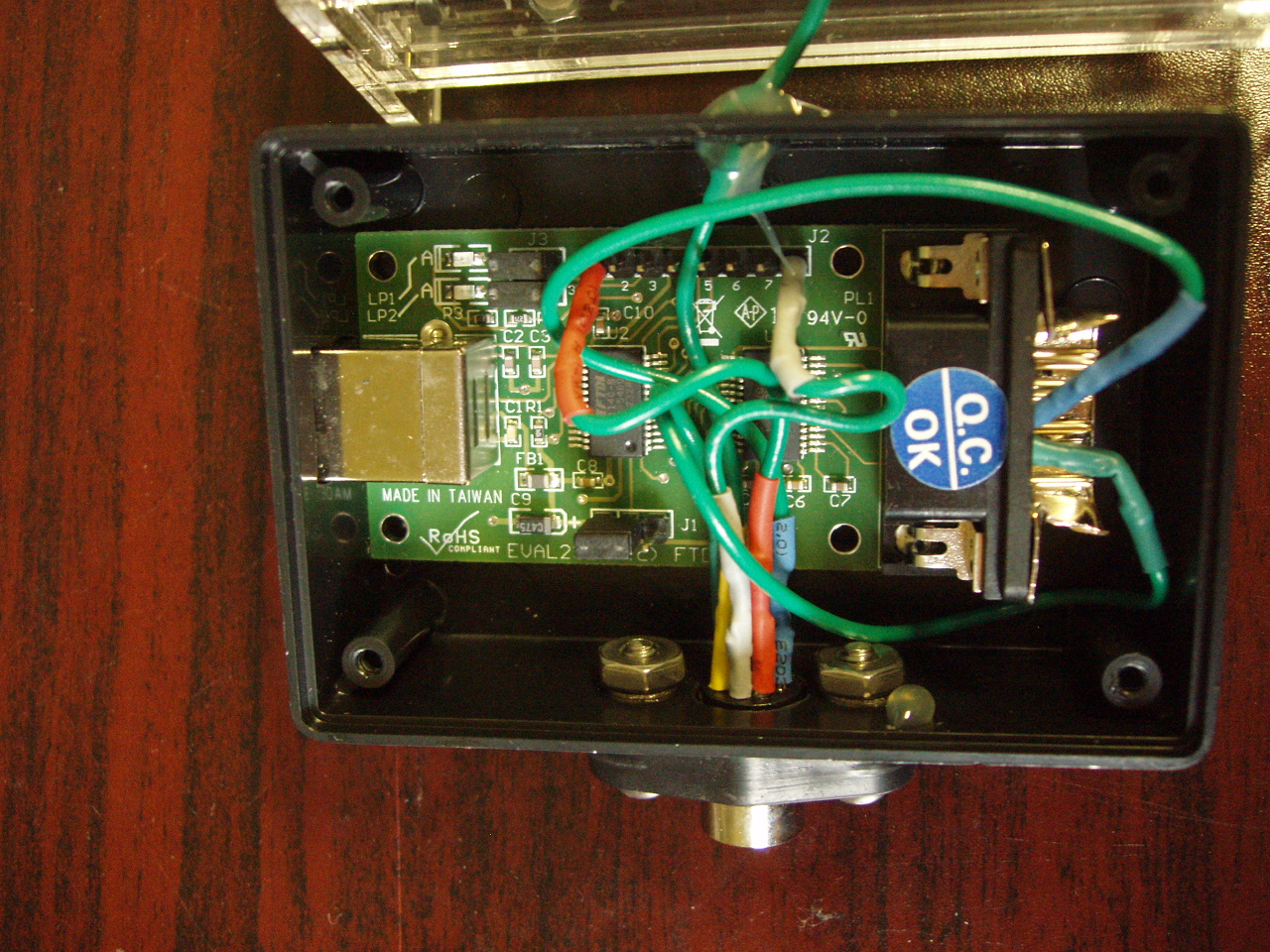
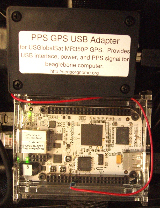
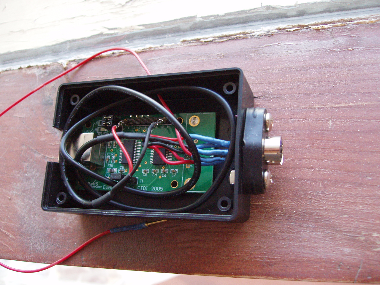
Photos of Example Project Box
Here is a simple project box that achieves this - note the cut-away portion of the metal housing on the DB-9 connector. The EVAL232R board is simply heat-glued to the bottom of the project box, into which appropriate The wire emerging from the top side of the box gets plugged into pin 15 of header P9 on the beaglebone computer:
Reprogramming the EVAL232 Board so it is recognized as a PPS-GPS by the SensorGnome
Note: this step requires a computer running Windows with Microsoft .NET 4.0 framework, because FTDI doesn't provide a Mac version of their FTPROG utility. Details
Internal software details (for SensorGnome developers)
gpsctl -n -t SiRF /dev/ttyUSB0
# PPS support
#
CONFIG_PPS=y
# CONFIG_PPS_DEBUG is not set

#
# PPS clients support
#
CONFIG_PPS_CLIENT_KTIMER=y
# CONFIG_PPS_CLIENT_LDISC is not set
# CONFIG_PPS_CLIENT_PARPORT is not set
CONFIG_PPS_CLIENT_GPIO=y
Was this page helpful?
Tags: (Edit tags)
|
|||||||||||||||||||||||||||||||||||||||||||||||||||||||||||||||||||||||||||||||
Powered by MindTouch Core |
||||||||||||||||||||||||||||||||||||||||||||||||||||||||||||||||||||||||||||||||