|
|
How do I build a SensorGnome? How do I build a SensorGnome?Edit
From $1
Table of contentsNo headersParts.
Instructions.
- Drill hole in Pelican Case for portal fittings. We use a 1 7/8" (48 mm) hole saw for the 1.5" male and female cleanout adapters. For cases 1300 and 1400, the exact positioning of the portal fittings isn't crucial, but should be approximately centered in the left wall of the case (all references to front, back, left, right apply to when the case handle is facing you). For case 1200, the smallest of the three, the center of the hole should be 41 mm from the lower lip of the case. Once drilled, tidy up the hole by removing stringy case bits from the edges.
 
- Apply heat glue to the base of the threaded portion of the male cleanout adapter and insert the adapter into the hole from inside the case (the threaded portion of the male adapter should protrude from the outer wall of the case). While the heat glue is still liquid, screw on the female adapter from the outside of the case. Once the female adapter has been screwed on tight, apply heat glue to where the base of the female adapter meets the outer wall of the case. Attach test cap to female adapter.
 
 
- Heat glue barrier block to front left corner of Pelican Case floor. Leave ~ 35 mm of space between barrier block and left wall of Pelican Case for ring terminals and speaker wire connecting to the DC/DC voltage converter. Label positive/negative terminals of barrier block.
 
- Label DC/DC voltage converter and attach to left wall of Pelican Case using adhesive-backed Velcro.
  
 
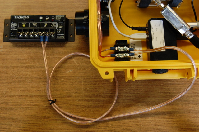
- Connect barrier block to voltage converter. Cut a piece of 16 AWG speaker wire long enough to reach from the barrier block to the positive/negative terminals on the "From: Battery to Solar Charge Controller" side of the voltage converter. Strip 5-7 mm at each end of the wire. Attach (crimp) ring terminals to one end of the wire and secure rings to barrier block. Leave the other end of the wire bare and insert into positive/negative terminals of the voltage converter. Make sure the positive barrier block terminal connects to the positive voltage converter terminal, and the negative barrier block terminal connects to the negative voltage converter terminal. Secure middle of wire to top of portal fitting with heat glue.

 
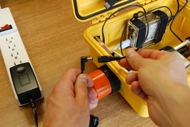
- Cut approximately 30 cm from the power cable with male DC plug and strip 5-7 mm of cable at non-plug end. Insert stripped ends into positive/negative terminals on the "To: Y cable: USB hub and BeagleBone" side of the voltage converter. The positive wire is marked with white dashes.
 
- To prevent the DC power cable from bending where it connects to the positive/negative terminals of the voltage converter, fasten the cable to the left wall of the Pelican Case with Velcro. First cut a ~ 4 cm piece of adhesive-backed Velcro (the fuzzy side) and then cut the piece in half, lengthwise. Next, cut ~ 1 cm off either end of one piece. At this point you should have two skinny pieces of Velcro; one ~ 4 cm in length and one ~ 2 cm in length. Remove the backing from Velcro and stick the two pieces together, centering the shorter piece on the longer piece. Lastly, fasten the DC power cable to the left wall of the case, just above the voltage converter.
   
- Assemble BeagleBone enclosure (instructions can be viewed here). Be careful not to overtighten the bolts -- slightly tighter than hand tight is fine. Overtightening can crack the acrylic enclosure.

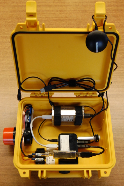
- NEW: attach the beaglebone in flat position, with the circuit board pointing down, not on its side as is shown here..Attach BeagleBone to back center of Pelican Case floor using double-sided Velcro and heat glue. First, cut two 25 cm pieces of double-sided Velcro. Apply ~ 2cm of heat glue to the non-fuzzy side of one of the Velcro pieces, 8-10 cm from the end. Attach the Velcro to the floor of the Pelican case, slightly left of center and ~ 2cm from the back wall of the case, with the longer half of the Velcro strip towards the back of the case. Repeat for the second piece of Velcro, except position the Velcro slight right of center this time. The two pieces of Velcro should be separated by ~ 4.5 cm. Use the Velcro to secure the BeagleBone to the floor of the Pelican Case. Position the Beaglebone such that the microSD slot and USB port face the voltage converter and with the microSD slot above the USB port.
 
 
- Label USB Port Hub and attach to front center of Pelican Case floor using adhesive-backed Velcro.
  
 
- Connect BeagleBone to USB Port Hub with the 3' USB A to B cable (male/male) that comes with Port Hub. Shorter USB A to B cables can be purchased separately, like the 6" cable in the photo below. Shorter cables may be preferable for Pelican Case models 1200 and 1300.

- Connect Y cable to BeagleBone and USB Port Hub.

- Insert Survivor Flash Drive into USB Port Hub.

- Insert USB GPS into USB Port Hub. Instructions for connecting a high-accuracy GPS can be found here.

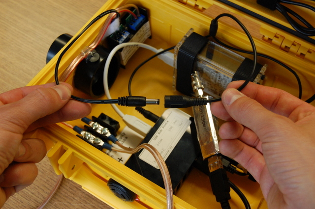
- Connect USB to mini USB cable (male/male) to BeagleBone. When not in use, the cable can be wrapped in double-sided Velcro and stuck to the straps holding the BeagleBone in place.
 
- Wrap FUNcube Dongle(s) in aluminum tape and attach BNC-SMA adapter. The aluminum tape should cover the plastic portion of the FUNcube but not be in contact with the metal of the USB connector and SMA connector. Write the serial number oof the FUNcube on the alumuinum tape.
 
- Connect FUNcube Dongle(s) to USB extension cable A to A (male/female) and then connect the extension cable to the USB port hub.

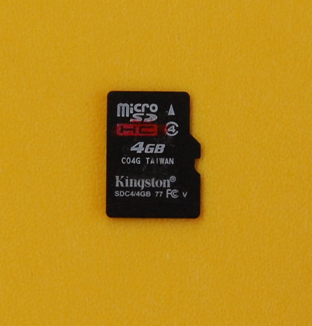
- Carefully insert a microSD card with SensorGnome software into the BeagleBone SD card slot.

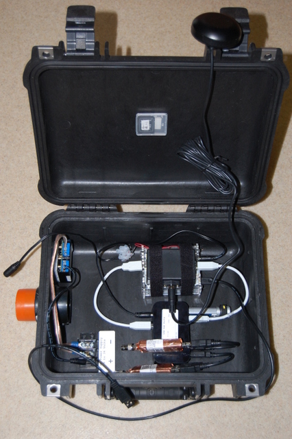
- That's it. You're now ready to power up your SensorGnome.
| File | Size | Date | Attached by | |
|---|
 | | 6 in USB-USB.JPG No description | 176.24 kB | 15:30, 3 Nov 2014 | admin | | | | AC Power.JPG No description | 184 kB | 15:31, 3 Nov 2014 | admin | | | | Barrier Block 1.JPG No description | 143.85 kB | 15:30, 3 Nov 2014 | admin | | | | Barrier Block 2.JPG No description | 117.22 kB | 15:30, 3 Nov 2014 | admin | | | | Barrier Block to Voltage Converter 1.JPG No description | 121.12 kB | 15:30, 3 Nov 2014 | admin | | | | Barrier Block to Voltage Converter 2.JPG No description | 137.64 kB | 15:30, 3 Nov 2014 | admin | | | | Barrier Block to Voltage Converter 3.JPG No description | 136.99 kB | 15:30, 3 Nov 2014 | admin | | | | BeagleBone 1.JPG No description | 176.04 kB | 15:30, 3 Nov 2014 | admin | | | | BeagleBone 2.JPG No description | 122.16 kB | 15:30, 3 Nov 2014 | admin | | | | BeagleBone 3.JPG No description | 183.34 kB | 15:30, 3 Nov 2014 | admin | | | | BeagleBone 4.JPG No description | 173.23 kB | 15:30, 3 Nov 2014 | admin | | | | BeagleBone 5.JPG No description | 158.85 kB | 15:30, 3 Nov 2014 | admin | | | | BLPW Fall 2012.JPG No description | 138.72 kB | 15:31, 3 Nov 2014 | admin | | | | DC Power 1.JPG No description | 169.44 kB | 15:31, 3 Nov 2014 | admin | | | | DC Power 2.JPG No description | 184.64 kB | 15:31, 3 Nov 2014 | admin | | | | Drilling Hole for Portal Fittings.JPG No description | 178.59 kB | 15:30, 3 Nov 2014 | admin | | | | FCD 1.JPG No description | 166.59 kB | 15:30, 3 Nov 2014 | admin | | | | FCD 2.JPG No description | 181.38 kB | 15:30, 3 Nov 2014 | admin | | | | FCD 3.JPG No description | 160.08 kB | 15:31, 3 Nov 2014 | admin | | | | Flash Drive.JPG No description | 181.07 kB | 15:30, 3 Nov 2014 | admin | | | | Inner Double Head Shot.JPG No description | 161.85 kB | 15:31, 3 Nov 2014 | admin | | | | microSD 1.JPG No description | 166.86 kB | 15:31, 3 Nov 2014 | admin | | | | microSD 2.JPG No description | 172.76 kB | 15:30, 3 Nov 2014 | admin | | | | Portal Fittings 1.JPG No description | 122.77 kB | 15:30, 3 Nov 2014 | admin | | | | Portal Fittings 2.JPG No description | 164.36 kB | 15:30, 3 Nov 2014 | admin | | | | Portal Fittings 3.JPG No description | 162.44 kB | 15:30, 3 Nov 2014 | admin | | | | Portal Fittings 4.JPG No description | 137.33 kB | 15:30, 3 Nov 2014 | admin | | | | Portal Location for Pelican Case 1200.JPG No description | 144.93 kB | 15:30, 3 Nov 2014 | admin | | | | SensorGnome 1.JPG No description | 177.28 kB | 15:31, 3 Nov 2014 | admin | | | | SensorGnome.JPG No description | 174.42 kB | 15:30, 3 Nov 2014 | admin | | | | USB - mini USB 2.JPG No description | 184.05 kB | 15:31, 3 Nov 2014 | admin | | | | USB - mini USB.JPG No description | 188.13 kB | 15:31, 3 Nov 2014 | admin | | | | USB GPS.JPG No description | 164.65 kB | 15:31, 3 Nov 2014 | admin | | | | USB Port-Hub 1.JPG No description | 124.44 kB | 15:30, 3 Nov 2014 | admin | | | | USB Port-Hub 2.JPG No description | 137.85 kB | 15:30, 3 Nov 2014 | admin | | | | USB Port-Hub 3.JPG No description | 150.27 kB | 15:30, 3 Nov 2014 | admin | | | | USB Port-Hub 4.JPG No description | 161.87 kB | 15:30, 3 Nov 2014 | admin | | | | USB Port-Hub 5.JPG No description | 165.09 kB | 15:30, 3 Nov 2014 | admin | | | | Voltage Converter 1.JPG No description | 219.14 kB | 15:30, 3 Nov 2014 | admin | | | | Voltage Converter 10.JPG No description | 116.87 kB | 15:30, 3 Nov 2014 | admin | | | | Voltage Converter 11.JPG No description | 153.42 kB | 15:30, 3 Nov 2014 | admin | | | | Voltage Converter 2.JPG No description | 222.77 kB | 15:30, 3 Nov 2014 | admin | | | | Voltage Converter 3.JPG No description | 230.54 kB | 15:30, 3 Nov 2014 | admin | | | | Voltage Converter 4.JPG No description | 119.06 kB | 15:30, 3 Nov 2014 | admin | | | | Voltage Converter 5.JPG No description | 131.27 kB | 15:30, 3 Nov 2014 | admin | | | | Voltage Converter 6.JPG No description | 123.19 kB | 15:30, 3 Nov 2014 | admin | | | | Voltage Converter 7.JPG No description | 155.31 kB | 15:30, 3 Nov 2014 | admin | | | | Voltage Converter 8.JPG No description | 117.79 kB | 15:30, 3 Nov 2014 | admin | | | | Voltage Converter 9.JPG No description | 123.11 kB | 15:30, 3 Nov 2014 | admin | | | | Y cable.JPG No description | 179.06 kB | 15:31, 3 Nov 2014 | admin | |
|